

Overview
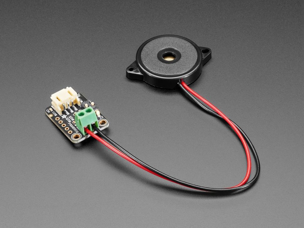
Piezos are simple to use, but getting them loud—or driving them at ultrasonic frequencies—usually needs more than a microcontroller pin can deliver. That’s where the Adafruit PAM8904 STEMMA Piezo Driver shines. This breakout is built around the PAM8904, a dedicated piezo driver IC designed specifically to push piezo elements far beyond standard PWM outputs.
Unlike traditional audio amplifiers, the PAM8904 is optimized for piezo loads and works up to 300 kHz, making it ideal for both audible buzzers and ultrasonic distance-sensing applications. The onboard switched-capacitor boost circuit and bridge-tied load (BTL) output allow it to multiply voltage internally, delivering up to ~13V peak-to-peak from a low-voltage supply.
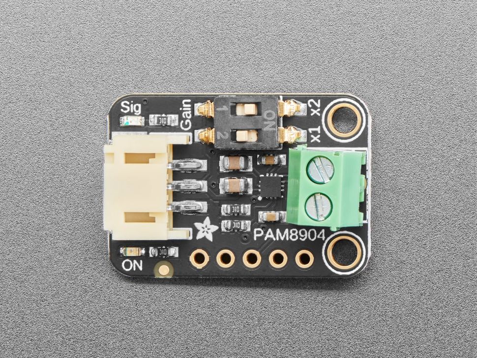
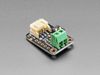
Using it is straightforward: power the board with 3–5 VDC, feed in a square-wave signal (20 Hz to 300 kHz), and connect your piezo to the output terminal block. A built-in dual DIP switch lets you select the gain—off, 1×, 2×, or 3×—so you can tune the output level for your application. Since the output is differential, higher gain settings dramatically increase the effective peak-to-peak voltage across the piezo.
Whether you’re building ultra-loud alerts, experimenting with ultrasonic ranging, or driving piezos at higher voltages safely, this breakout gives you a compact and reliable solution.
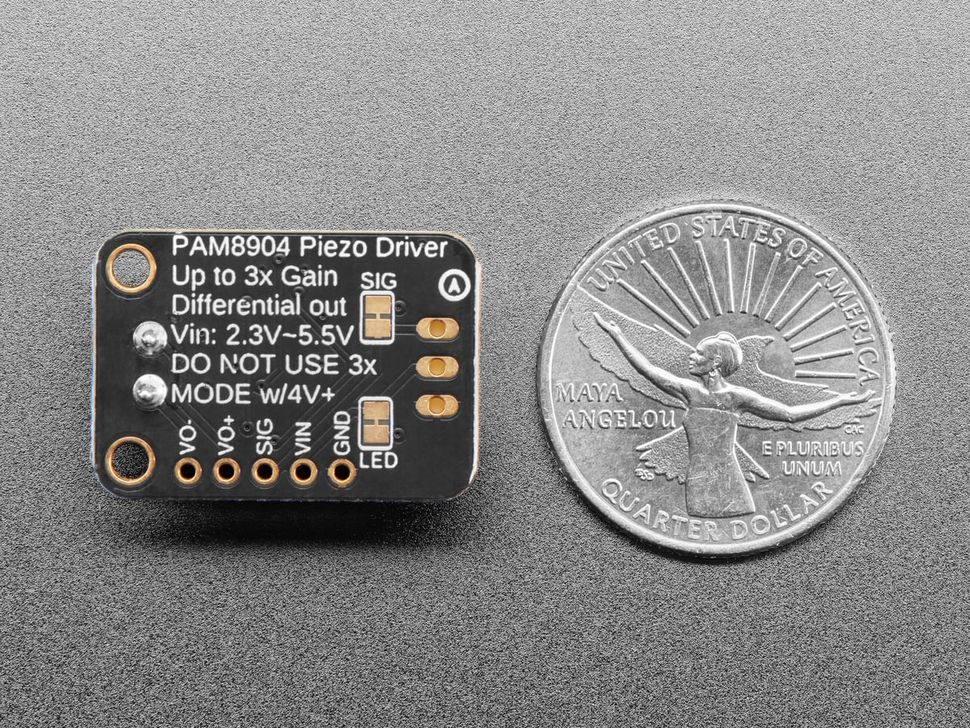
When powered from 5 V, do not use the 3× gain setting as the resulting voltage exceeds the chip’s rated limits. At 5 V, use 2× gain maximum (≈10 Vpp).
The 3× gain setting is safe when operating from 3.3 V, producing roughly 10 V output.
Specification
Technical details for Adafruit PAM8904 STEMMA Piezo Driver Audio Amplifier.
| Specification | Details |
|---|---|
| Driver IC | PAM8904 Piezo Driver |
| Designed For | Piezo buzzers and piezo transducers (audible & ultrasonic) |
| Operating Voltage (Vin) | 3 V to 5 V DC |
| Input Signal Type | Square wave / PWM |
| Input Frequency Range | 20 Hz to 300 kHz |
| Gain Settings | Off, 1×, 2×, 3× (via onboard dual DIP switch) |
| Output Configuration | Bridge-Tied Load (BTL), differential output |
| Maximum Output Voltage | Up to ~13 Vpp (gain and supply dependent) |
| Recommended Gain Limits | 3× gain safe at 3.3 V (~10 V output) 2× gain maximum at 5 V (~10 V output) |
| Voltage Boost Method | Internal switched-capacitor boost circuit |
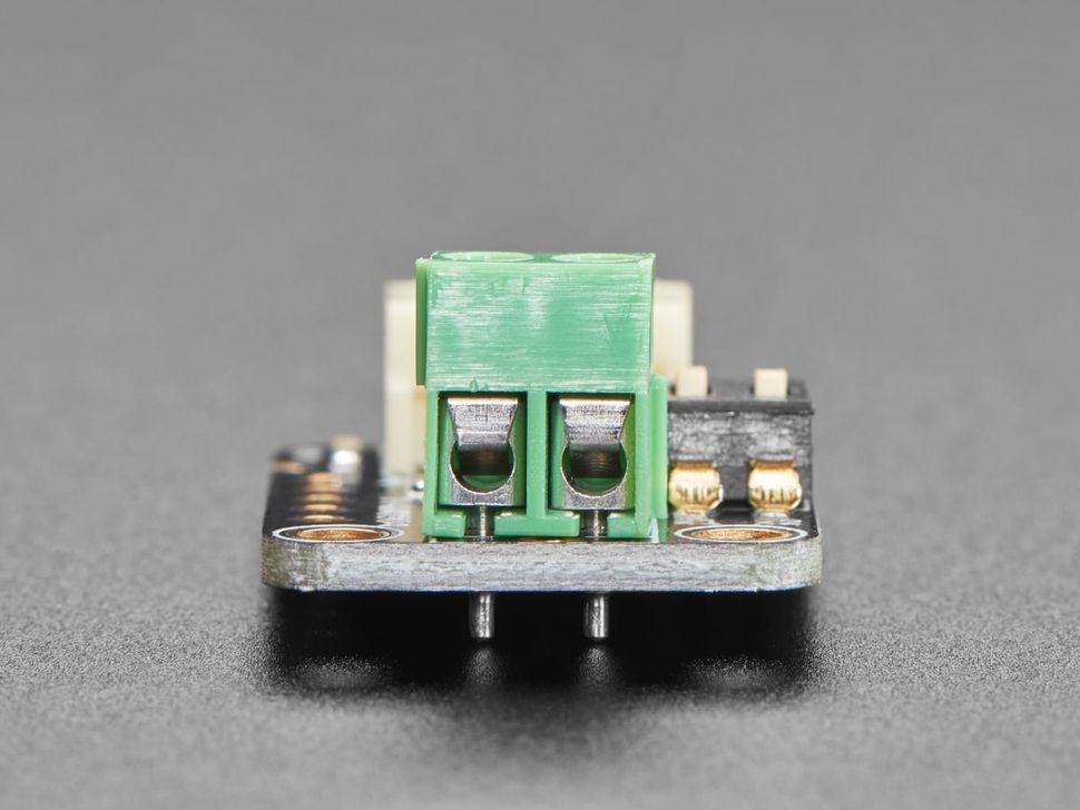
| Piezo Connection | Screw terminal block |
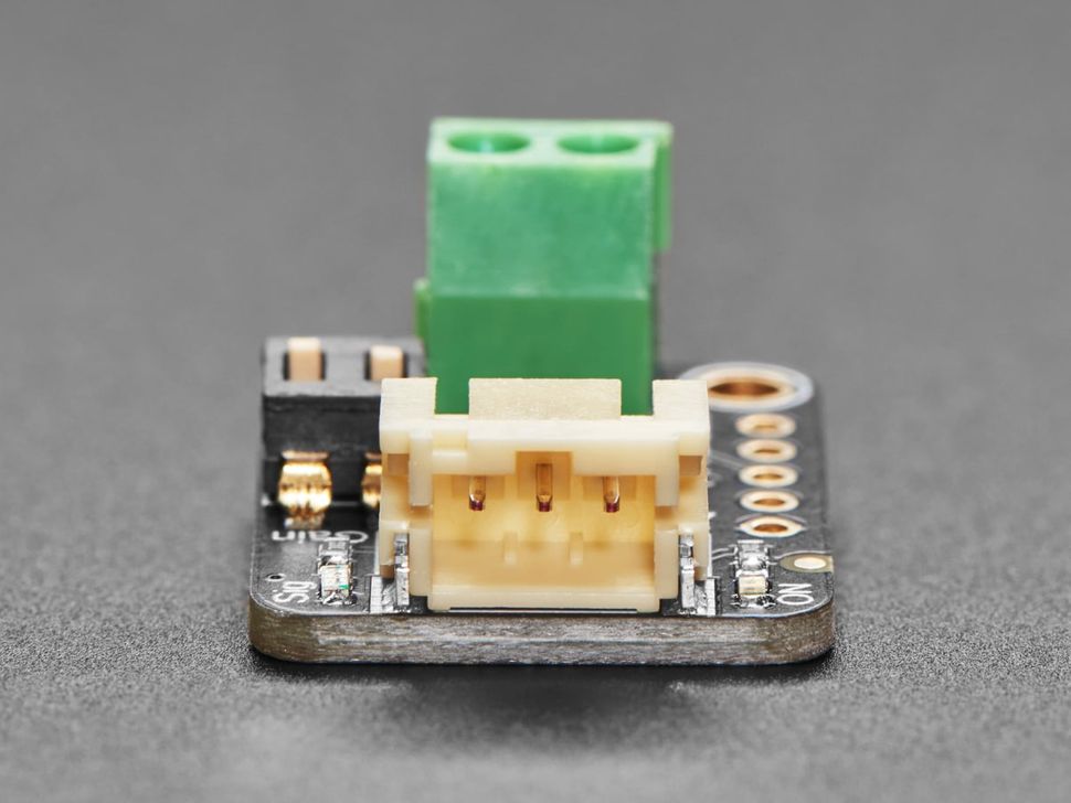
| Connector Type | STEMMA JST-PH, 2.0 mm pitch |
| Logic Compatibility | 3.3 V and 5 V logic microcontrollers |
| Typical Applications | Buzzers, alarms, ultrasonic distance sensing, haptics |
Pinout
| Pin / Connector | Label | Description |
|---|---|---|
| Power Pins | VIN | Power input pin. Supply between 2.3 V to 5 V DC. |
| GND | Common ground for power and logic. | |
| I/O Pins | SIG | Signal input pin. Provide a square wave from 20 Hz to 300 kHz. Signal voltage does not need to match VIN. |
| VO+ | Positive differential output for the piezo element. | |
| VO− | Negative differential output for the piezo element. | |
| STEMMA Connector (JST-PH 2.0 mm) |
SIGNAL (White wire) |
Signal input pin for square-wave or PWM control. |
| VIN (Red wire) |
Power input, typically 3–5 V DC. | |
| GND (Black wire) |
Ground reference for power and signal. | |
| Terminal Block | VO+ | Positive piezo output terminal. Located near the x1 label on the PCB silk. |
| VO− | Negative piezo output terminal. Located near the PAM8904 label on the PCB silk. | |
| Gain Selector | DIP Switch | Dual DIP switch to set output gain: • OFF = 0× gain • x1 switch ON = 1× gain • x2 switch ON = 2× gain • x1 + x2 ON = 3× gain Note: Differential output means 2× gain results in ~4× VIN peak-to-peak across the piezo. |
Opps
Sorry, it looks like some products are not available in selected quantity.
Reviews
No reviews have been written for this product.